

OVERVIEW
DAC-CLIP is a vintage digital-to-analog converter emulation and clipper. It runs one signal chain in four stages: input drive (saturation), CONVERT (bit-depth and sample-rate reduction with dither), a multi-mode filter, and a hard-knee output clipper. The goal is the sound of old samplers and converters, and the way those early output stages clipped against their fixed voltage limits.
Three terms appear throughout. Bit depth is how many amplitude levels a sample can take: fewer bits means coarser steps and more audible quantization grit. Sample rate is how many samples per second the converter runs at: lowering it folds high frequencies back down as aliasing. Dither is low-level noise added before quantization that trades harsh stair-step distortion for a smoother noise floor.
The plugin runs in stereo or mono. The DRIVE, CONVERT, and FILTER bays each have an enable box in their header, and the whole effect has a global BYPASS and a dry/wet MIX. The AUTO-GAIN button measures input against output level and sets the output gain so you can compare at matched loudness. The four drive curves are labeled M1 to M4 on screen, voiced after a tube preamp (M1), an SP-1200 (M2), an MPC3000 (M3), and a Neve 1073 (M4). They are perceptual curves, not circuit models.
INTERFACE
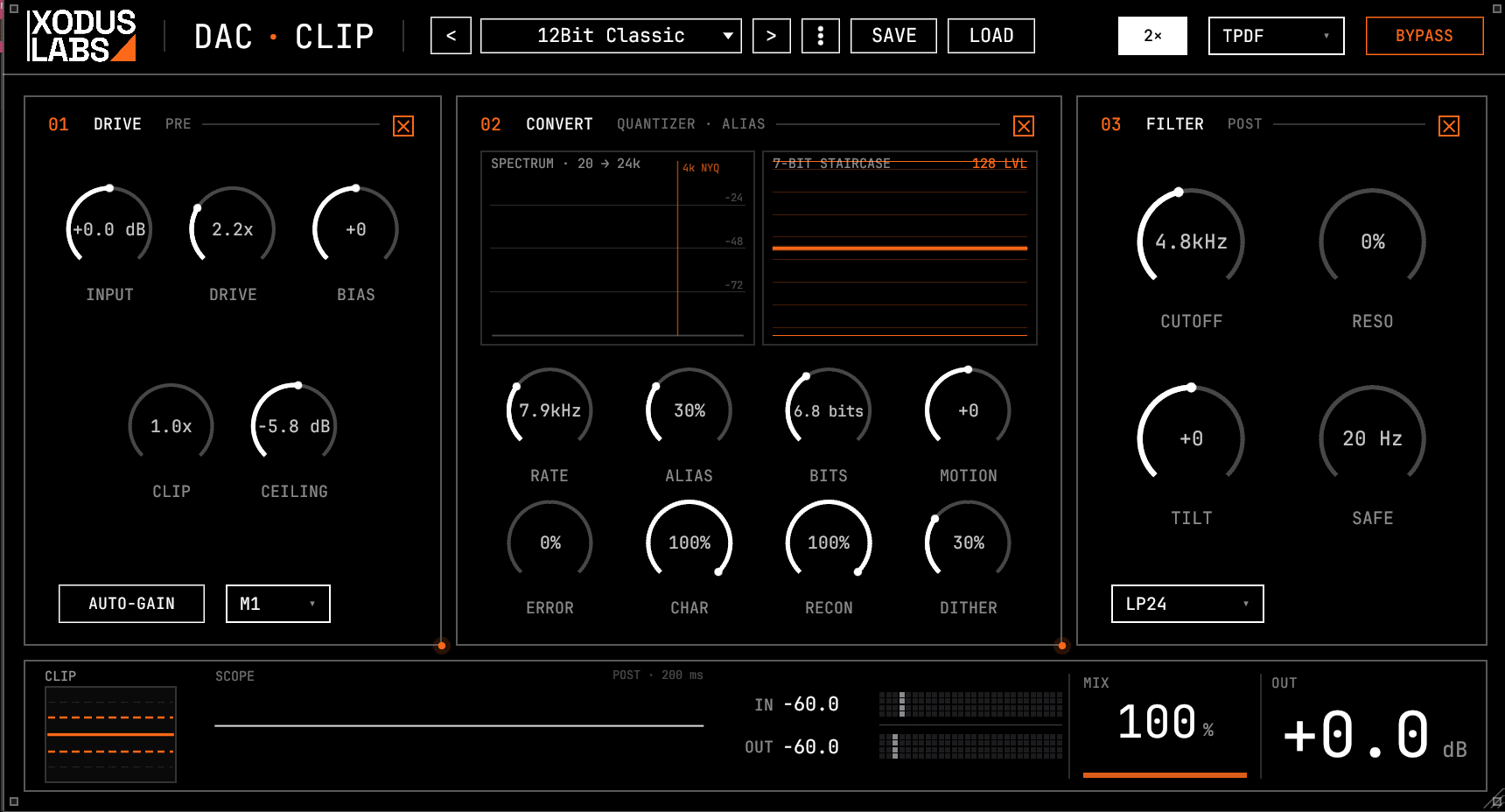
SIGNAL CHAIN
The order in which DAC-CLIP processes the signal, from input to output.
- 01INPUT trim, applied to the dry signal
- 02SAFE band-split: content at and below the SAFE cutoff is routed around the whole chain and rejoined at the end
- 03MOTION envelope follower tracks the signal and modulates the effective bit depth
- 04DRIVE saturation (model M1 to M4), when the drive bay is enabled
- 05CONVERT, quantize: bit-depth reduction with CHAR companding, DITHER, and ERROR converter warp
- 06CONVERT, sample rate: anti-alias filter (swept by ALIAS), then decimation with RECON reconstruction
- 07FILTER: TILT EQ, then the selected filter mode
- 08DAC clipper: BIAS offset, CLIP drive into the fixed rails, then BIAS removed
- 09CEILING hard limit, then the SAFE low band summed back in
- 10Dry/wet MIX, then OUTPUT GAIN
CONTROLS
DRIVE
| Control | Range | Default | Description |
|---|---|---|---|
| INPUT | -12..+12 dB | 0 | Input trim applied before the whole chain.Sets how hard the signal enters the converter and clipper without touching the source. INPUT stays live even when the drive bay is switched off, so it works as a clean level trim into the rest of the chain. |
| DRIVE | 1.0..4.0 x | 1.0 | Input saturation amount, feeding the selected drive model.At 1.0 the path is clean; pushing up adds harmonics and color through the chosen M1 to M4 curve. The knob has finer control at the low end, where most useful drive lives. |
| DRIVE MODEL | M1 / M2 / M3 / M4 | M1 | Selects which saturation curve the DRIVE knob feeds.M1 is a soft tube-style clip that stays mostly clean even at full drive. M2 is a crunchy SP-1200 voicing with mid emphasis that bites early. M3 is an MPC3000 voicing that compresses dynamics and thickens the low-mids. M4 is a Neve 1073 voicing with a strong second harmonic, the most colored option. The curves are level-matched so you can compare without volume jumps. |
LOFI
| Control | Range | Default | Description |
|---|---|---|---|
| BITS | 4..24 bits | 12 | Bit depth of the quantizer.Lower bits mean coarser amplitude steps and more audible quantization crunch. The knob has more resolution over the lower, more audible range (about 4 to 12 bits). Above about 14 bits the effect is largely inaudible on most material. |
| CHAR | 0..100 % | 50 | Companding amount applied around the quantizer.Companding gives quiet signal more quantization levels and loud transients coarser steps, the classic sampler punch. At 0 it is a clean linear quantize; at 100 it is full mu-law companding. |
| RATE | 4000..48000 Hz | 16000 | Target sample rate the decimator reads out at.Lowering it produces stepped sample-and-hold artifacts and folds highs back down as aliasing, the core lo-fi sampler sound. The knob has more resolution at the low end. At or above the host rate it passes through cleanly. |
| ALIAS | 0..100 % | 30 | Anti-alias filter harshness before the decimator.At 0 a clean low-pass sits well below the target rate so downsampling stays smooth; at 100 the filter opens up so the first alias band passes almost unfiltered for raw vintage grit. |
| RECON | 0..100 % | 50 | Reconstruction smoothing applied to the held samples.At 0 it is a pure zero-order hold, the chunky stair-step output of cheap converters like the SP-1200; at 100 it is a smooth reconstruction for high-end DAC clarity. |
| DITHER | 0..100 % | 30 | Amount of dither noise mixed into the quantizer.Dither trades harsh quantization distortion for a smoother low-level noise floor, most useful at low bit depths. The shape is set by DITHER MODE; at 0 no noise is added regardless of mode. |
| DITHER MODE | NONE / TPDF / NOISE | TPDF | Noise shape used by the DITHER amount knob.NONE disables dither. TPDF is triangular dither, the standard choice that decorrelates the quantization error from the signal. NOISE is a heavier variant for an audible fuzz. |
| MOTION | -100..+100 | 0 | Envelope-driven dynamic bit-depth modulation.At 0 it is off and identical to a static setting. Positive values crush quiet material so loud hits stay clean and tails fade to grit, the sound of old samplers truncating decays; negative values invert that. It is only active when the CONVERT section is enabled. |
FILTER
| Control | Range | Default | Description |
|---|---|---|---|
| FILTER MODE | OFF / LP6 / LP12 / LP24 / BAND | LP24 | Selects the filter topology. OFF disables the bay.LP6 is a gentle single-pole low-pass (about 6 dB per octave), LP12 a 12 dB per octave low-pass, LP24 a 4-pole Moog-style ladder (about 24 dB per octave), and BAND a bandpass at the cutoff. OFF also disables the TILT EQ. |
| CUTOFF | 1000..20000 Hz | 8000 | Cutoff or center frequency of the active filter mode.For the low-pass modes this is where the highs start rolling off; for BAND it is the center of the passband. The knob has more resolution at the low end, where tone shaping is most sensitive. |
| RESO | 0..100 % | 0 | Filter resonance at the cutoff.Raising it emphasizes the frequencies around the cutoff. For LP12 and BAND the Q climbs steadily; the LP24 ladder takes its own resonance for the classic self-emphasizing peak. LP6 has no resonance. |
| TILT | -100..+100 | 0 | Broad tonal tilt EQ at the filter input, pivoting near 700 Hz.Negative values tilt the tone darker (lows up, highs down) and positive values tilt it brighter, roughly 3 dB at the extremes. It is disabled when FILTER MODE is OFF. |
| SAFE | 20..500 Hz | 20 | Bass-safe cutoff that routes the low end around the whole chain.Content at and below this frequency is split off the input and bypasses drive, quantization, sample-rate reduction, the filter, and the clipper, then is summed back at the end so the sub and kick stay clean while the upper band is processed. At the 20 Hz minimum almost nothing is captured; raise it to protect more low end. |
CLIP
| Control | Range | Default | Description |
|---|---|---|---|
| CLIP | 1.0..4.0 x | 1.0 | Drive into the fixed rails of the output clipper.The clipper rails are fixed and slightly asymmetric, so this knob sets how hard the signal is pushed into them and therefore how much hard clipping and density you get. There is no makeup gain, like hardware, so use AUTO-GAIN or OUTPUT GAIN to level-match. |
| BIAS | -100..+100 | 0 | Asymmetric clip bias, adding a DC offset before the clipper.It shifts the operating point so one rail clips earlier than the other, producing asymmetric saturation and even-harmonic color. The offset is added before the clipper and removed after. At 0 the path is unaffected. |
| CEILING | -12..0 dB | 0 | Hard output ceiling applied after the clip stage.A fixed hard limit, not a soft knee: the chain output is clamped to this level. Lowering it squashes the waveform against the rails in the clip scope. CEILING stays live even when the drive bay is off. |
| ERROR | 0..100 % | 0 | Converter transfer-curve error modeling.It applies a deterministic warp of the converter curve: a smooth tired-converter bow plus a light per-step grit. It tracks the signal rather than adding hiss, so silence stays silent. |
OUTPUT
| Control | Range | Default | Description |
|---|---|---|---|
| OVERSAMPLE | OFF / 2X | OFF | Oversampling around the saturation and clipper stages.2X runs the companding path and the clipper through an oversampler to reduce aliasing from those nonlinear stages, crossfaded on toggle to avoid clicks. Use it for cleaner high-drive clipping at the cost of some CPU. |
| OUTPUT GAIN | -30..+30 dB | 0 | Final output level (the large OUT readout).Sets the level after the dry/wet mix, and is what AUTO-GAIN adjusts to match the processed output back to the input. Drag the big OUT number to change it. |
| MIX | 0..100 % | 100 | Global dry/wet blend for the whole chain.An equal-power crossfade between the untouched input and the processed signal, so the perceived loudness stays steady across the sweep. Use it for parallel processing, blending grit under a clean signal. |
| BYPASS | Off / On | Off | Bypasses all plugin processing.When on, the input passes straight to the output. Pair it with AUTO-GAIN for a level-matched comparison. |
WORKFLOWS
Lo-fi a drum loop
- 01Enable the CONVERT bay and set BITS down to about 10 to 12 for audible crunch.
- 02Lower RATE toward 12 to 20 kHz for the stepped sampler tone.
- 03Pull RECON toward 0 for chunky zero-order-hold steps, or up for a smoother converter.
- 04Add a little ALIAS for raw top-end grit, and set DITHER to taste to soften harshness.
- 05Set SAFE around 80 to 120 Hz to keep the kick and sub clean.
Saturate a bass
- 01Set DRIVE MODEL to M3 for warm compression, or M4 for transformer color.
- 02Raise DRIVE until the low-mids thicken without losing definition.
- 03Add a touch of BIAS for asymmetric, even-harmonic body.
- 04Set SAFE around 40 to 60 Hz so the deep sub stays clean while the upper band is colored.
- 05Press AUTO-GAIN to level-match, then compare with BYPASS.
Hard-clip a bus or master
- 01Leave the CONVERT bay off if you only want clipping.
- 02Make sure the drive bay is enabled and raise CLIP to push the signal into the fixed rails.
- 03Lower CEILING to set the ceiling and watch the clip scope squash against it.
- 04Turn OVERSAMPLE to 2X to reduce aliasing from the hard clipping.
- 05Use OUTPUT GAIN or AUTO-GAIN to match level for an honest before and after.
Vintage sampler sound
- 01Set DRIVE MODEL to M2 and add moderate DRIVE for the crunchy, mid-forward bite.
- 02Enable CONVERT, set BITS near 12 and RATE near 26 kHz.
- 03Set RECON to 0 for pure zero-order-hold stair-steps.
- 04Raise CHAR toward full companding for sampler punch, and add ERROR for a tired-converter color.
- 05Blend with MIX if you want the grit to sit under the dry signal.
GOOD TO KNOW
- 01The ERROR knob models a static converter-curve error, not clock jitter or drift. It produces deterministic, signal-tracking color rather than hiss, and silence always stays silent.
- 02Quantization happens before sample-rate reduction, like real samplers that store quantized data and read it out at the target rate. BITS and CHAR shape the data, then RATE and RECON shape how it plays back.
- 03SAFE is the one control that ignores the bay enable boxes: it always routes the low end around the whole chain and sums it back, so the sub and kick stay clean no matter what the rest is doing.
- 04The clipper rails are fixed and slightly asymmetric, which adds subtle even harmonics on its own. CLIP sets how hard you hit the rails; CEILING sets the final hard clamp after them.
- 05MOTION only works while the CONVERT section is enabled, and at 0 it is identical to a static bit depth, so engaging it never causes a jump.
- 06AUTO-GAIN measures input and output over a short window and sets OUTPUT GAIN to match them, which keeps BYPASS comparisons fair instead of louder-sounds-better.